Wayne Mendenhall on: Evaluating Power Supply Options
Designing Power systems has become a much more challenging task than ever before. There are many considerations
when designing a modern DC-DC power supply. Wider voltage ranges, higher current consumption and the requirement for
multiple voltage rails has also resulted in a new set of design requirements and related issues. Fortunately for
designers, there now exists a wide array of very exciting circuit options to overcome these challenges. We will
discuss the challenges and potential circuit options in detail.
Choosing the Correct Type of Power Supply
There are three main types of power IC structures commonly used by hardware designers: linear regulators (LDOs),
switching regulators (boost and buck) and charge pumps. All work off very different design structures, offering
different characteristics. The benefits and shortfalls help to determine which power supply is most suitable for an
application. For example, linear regulators have a very low-noise, stable voltage output. However, they can only
regulate from a higher voltage supply to a lower voltage and are highly inefficient. Switching regulators offer
greater efficiency, can step-up (boost) a voltage, step-down (buck) a voltage or invert the polarity of the supply
voltage. However, switching regulators require external components such as capacitors and inductors, and they emit
EMI. Similarly, charge pumps step up, step down and invert input voltages, but they have limited output-current
capability. Let’s take a closer look at these power supplies and their characteristics.
Electro Magnetic Interference EMI
Electro Magnetic Interference (EMI) is a negative characteristic associated with switching power supplies. EMI is a
large consideration for systems with low level signals, where EMI can affect the signal quality and degrade system
performance. There are many system designs that require high efficiency and are very sensitive to EMI. IC design
techniques have been developed to help reduce EMI while retaining high efficiency. Some manufacturers have begun
using a spread spectrum implementation on the switching clock to reduce the EMI, allowing these products to achieve
EN55022 Class A limits. By dithering the internal clock frequency at some small percentage of the fundamental, the
energy stored in the fast dv/dt of the clock pulse causing the EMI is flattened over a wider time frame, reducing
the level of EMI. An example of such an implementation is shown below. This approach allows better system
performance, making the end equipment more robust. Figures 1 and 2 show the effect of dithering the clock and the
EMI performance for this technique implemented in the MAX1724 synchronous boost converter.
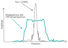
Figure 1: Effect of clock dithering in MAX17243
Figure 2: EMI performance for MAX17243
Line Noise Suppression
In most industrial environments the AC line is not a noise free, clean source. This is because the same line that
feeds a power supply is also used to drive larger equipment. Motors, solenoids and relay controls require higher
levels of current when they are powered on than during continuous operation. Large disturbances such as power sags
and surges are commonplace. With automated industrial controls, particularly those that employ programmable logic
controllers (PLCs), 12V or 24V DC are the most common backplane voltages used. The backplane voltage is stepped down
to the lower voltage levels demanded by the individual components (Figure 3). To make things just a little more
complicated, a designer needs to take into account transient voltage spikes ("over-voltages") that affect the mains
supply. Examples include events such as lightning strikes on the distribution network or rapid switching of heavy
loads that share the same mains circuit, such as with industrial automation systems. Voltage spikes can also occur
within the power-supply architecture itself, for example, when the power module steps down the mains voltage to
12VDC/24VDC or to lower voltages for the CPU and FPGA supplies, particularly if a switch-mode device is used.¹
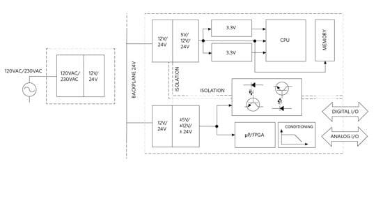
Figure 3: Part of the power architecture for an industrial automation
system.
For this reason, companies such as Maxim Integrated are investing in a portfolio of power supplies that enhance
system performance and cost in the area of high voltage transient suppression. By incorporating circuitry within the
power supply to suppress input transients, the designer does not need to be concerned with conditioning the raw DC
voltage. Synchronous boost power supplies available today easily handle wide input voltage ranges and generate very
clean, low ripple regulated outputs. The clean, regulated voltages ease the design task and reduce costs by allowing
the use of fewer, standard components and standard design methodologies. These power supplies are excellent choices
for point-of-load (POL) applications. Figure 4 gives a visual representation of such a system implemented using
Maxim’s latest generation of power products.
Figure 4: MAX17242/3 in a point-of-load application
Heat
One major concern has become heat generation. Heat manifests itself in the active current consumed by the system and
has other negative effects as well. The overall reliability of the entire system is affected by heat. Equipment that
runs cooler is more efficient and, ultimately, more reliable. Large amounts of heat require additional cooling which
in turn consumes more power. Mechanical fans needed to cool the system have high failure rates compared to the rest
of the system. Designers must disperse the heat to avoid hot spots on their boards that would exacerbate reliability
issues.
The ability to fit more functionality in a smaller footprint is always a driving force for system designers.
Advanced wafer processing technology, ultra-small packaging and the increasing trend of integrating external
components into the IC’s themselves have helped system designers along this path.
Synchronous conversion, as used by the latest generation of power supplies, guarantees not only high efficiency and
a tiny solution size, but dramatically reduces heat dissipation as well -- frequently by as much as 50%.
Synchronous architectures eliminate the need for an external Schottky diode by integrating a low-side MOSFET supply
(Figure 5).
Figure 5: Non-synchronous and synchronous regulator architectures
By also integrating compensation, the total solution size is reduced by as much by 50%. These features
significantly reduce board size, cooling requirements and cost. The recently introduced MAX17242/MAX17243 series of boost power supplies are available in a 20 pin
TQFN-EP package. They enable the implementation of a total power solution in an extremely small PC board space of
only 24mm x 19mm.
Mobility
The prevailing global trend of designing equipment in a mobile form factor makes battery life an important
consideration when designing power systems. In many markets, battery life can be a differentiating feature from one
manufacturer to another. Mobile system designers require very low quiescent currents to extend battery life as long
as possible. The emphasis for power supply vendors is now to develop ICs smaller in physical size while operating at
ultra-low power levels. An example of such a device is the MAX17242 boost converter which is optimized for low power
consumption applications. This device uses aggressive power savings techniques to reduce current consumption. These
ultra-low currents support smaller batteries and reduce the overall system cost. The switching frequency is resistor
programmable from 220kHz to 2.2MHz and can be synchronized to an external clock. This allows selection from a wide
variety of inductor sizes to best fit the application.
Tools
In the last several years, IC suppliers have begun producing very advanced power supply simulation tools. These
tools do an excellent job of predicting the performance of the power supplies in the end system across many
parameters, including temperature and load. These tools also help the system designer select the correct external
components, such as inductors and capacitors, for optimum performance of the entire power system. With all of the
considerations previously mentioned, tools such as Maxim’s EE-Sim Design and Simulation Tool are critical -
they help the system designer factor in all of the required variables to select the best power supply architecture
for an application. IC suppliers are continuing to enhance and improve these tools. Figure 6 shows an example of one
of the many types of analysis that Maxim’s state of the art EE-Sim tool can provide.
Figure 6: EE-Sim Waveform Viewer
Conclusion
Power regulation within electronic equipment today includes some very complex challenges. The parameters of heat,
EMI, noise, size and cost all factor into the design. Simply considering the cost of the individual power supply
solution is unlikely to be the best approach. The total system cost can be reduced by considering newer
technologies, such as synchronous boost converters, where board size, component count and thermal requirements can
be significantly reduced. New simulation tools are dramatically reducing design time and revisions while optimizing
the power regulation system. The added benefit will be a more reliable and robust system design. Maxim’s full
portfolio of power products and simulation tools can help to dramatically reduce cost, size and time to market in
your power regulation designs.
References
- The Industrial Automation Power Dilemma: Part 1 Industrial Control Architecture
Application Note 5784 Maxim Integrated Products, By Viral Vaidya. March 21, 2014


